1.6. DeviceNetSpecification for connection
1.6. DeviceNetSpecification for connection

Figure 1.4 DeviceNet Configuration of the network
(1) Terminating resistor
l If a termination resistor embedded in the BD525SUBD board is to be used (DSW1 Pin1 On), do not install an additional external termination resistor.
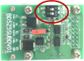
Figure 1.5 BD525SUBD Terminating resistor
l If a termination resistor embedded in the BD525SUBD board is not to be used (DSW Pin1 Off), install a resistor of 121 Ω (1%, 1/4 W), as shown in the following figure.
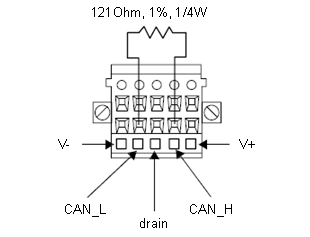
Figure 1.6 Installation of an external termination resistor
(2) Maximum length of the trunk line of each type
Communication speed | Flat cable | Thick cable | Mid cable | Thin cable |
125k bit/s | 420m | 500m | 300m | 100m |
250k bit/s | 200m | 250m | 250m | 100m |
500k bit/s | 75m | 100m | 100m | 100m |
Table 1‑4 Length of the trunk line of the DeviceNet
(3) Length of the drop line
Communication speed | Cumulative drop line length |
125k bit/s | 156m |
250k bit/s | 78m |
500k bit/s | 39m |
Table 1‑5 DeviceNet Length of the drop line
(4) Ground
l Ground the V conductor, shield, and drain lines at one locationto prevent ground loops. If possible, ground at a physical central location of the network to maximize the ground effects and minimize the effects of the external noise.
l When more than two power supplies are to be used, V+ should be cut off between the power supplies.
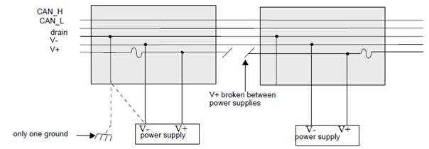
Figure 1.7 DeviceNet Installation