1.3. Appearance of the BD525 board
1.3. Appearance of the BD525 board
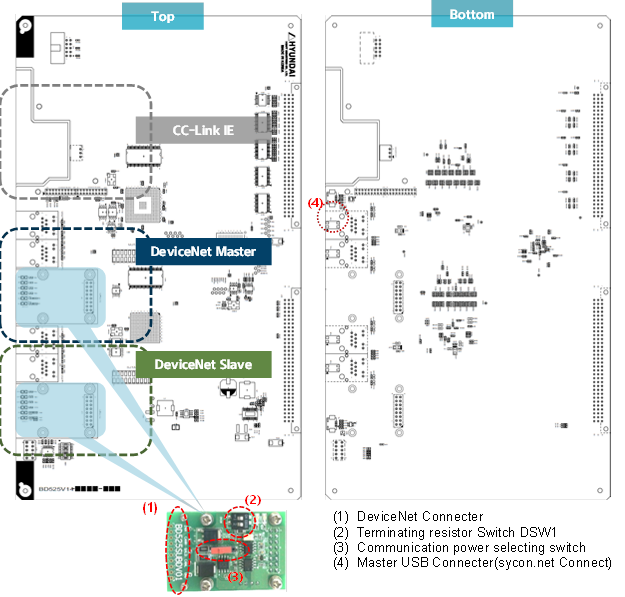
Figure 1.1 BD525 communication board
As the BD525 multi-protocol communication board can support industrial communication of up to three channels, including a CC-Link IE Field slave, a fieldbus or real-time Ethernet master, and a slave, at the same time. The board will be supplied after being assembled to include necessary channels.
To use the master and the slave of the BD525 DeviceNet, the sub-board (BD525SUBD) for the DeviceNet access should be mounted in piggyback form.
(1) DeviceNet Connecter

Figure 1.2 Connection of the BD525 DeviceNet cable
(2) Terminating resistor Switch DSW1
Pin number | 1 | 2 | |
Setting | OFF | Terminating resistor OFF | Not in use |
ON | Terminating resistor ON | Not in use | |
Appearance of the switch |
| ||

Table 1‑1 BD525SUBD Terminal resistor setting switch
(3) Communication power selection switch JP1
Always place JP1 in position ①, as shown in the following figure, and supply communication power (24VDC) from the outside. JP1 can be removed from the board without pre-notification.
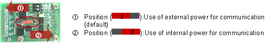
Figure 1.3 BD525SUBD Communication power selection switch
(4) Master USB Connecter(Sycon.net Connect)
For setting the network of the master of the BD525 DeviceNet, the Sycon.net software will be used. The set configuration information will be downloaded through the USB port. The master USB connector will be used for the USB connection between the PC with Sycon.net installed and the BD525 board.