2.3.4. Common coordinate setting
2.3.4. Common coordinate setting
If a common coordinate system is not set, it is not possible to operate the manual cowork jog or to make the cowork control. If a common coordinate system is set, it is recommended to try a cowork jog operation to check whether the system has been set correctly before starting the main operation.
The common coordinate setting is only possible when the accurate position of the cooperation robot tool end is known. Otherwise, a position synchronization error may occur during the cowork control of the robots. Therefore, you should carry out a calibration for the correct setting of the origin points and tools of the robots. The Hi5a controller features an automatic calibration function (“[F2]: System” → “6: Automatic Calibration” → “1: Optimize Axis Origin and Tool Length”) for cases where you have no 3-D position meter. If you have a 3-D position meter, you can make a more precise calibration. If you have a 3-D position meter, use the “9: Calibrate Robot and Tool” function. For more details please refer to the『Hi5a Controller operation manual』.
n Exemplary setting of a common coordinate system for two robots, Robot 1 and Robot 2
① For the controllers of Robot 1 and Robot 2, select a program number for the setting of a common coordinate system.
② By using each jog of Robot 1 and 2, record the 3 points to step 1, 2 and 3 in order to create a triangle, as large as possible. In this case, the identical spatial positions should be recorded. Although interpolation types and speed do not matter, tool numbers should be selected for the tools of which the edge positions are correctly identified.
③ Select 『[F2]: System』 → 『6: Automatic Calibration』→『5: Common coordinate of cooperate robots』in manual mode.
④ In the program number field, enter the program number for the setting of the common coordinate system.
⑤ Press the 『[F1]: Execute』 key. The results will be displayed in the screen through position and position of the common coordinate from robot base.
Press the 『[F7]: Complete』 key to complete the setting.
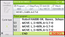

Figure2.7 Program for setting a common coordinate system for robots
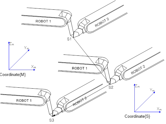
Figure2.8 Teaching method of common coordinate setting
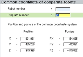
Figure2.9 Window showing the setting result of the common coordinate system

l With regard to the tool data values for setting the common coordinate system, enter the correct specifications of the tool or find the tool data value by using the automatic calibration. It is recommended that you record the identical position of the robots for each point.
l Record the points so that the three set points may form a triangle as large as possible. If the distance between two points is short or if the three points form a shape close to a straight line, an error will occur.
l The relationship of the position Rx, Ry and Rz of the common coordinate to the robot coordinate is as follows.
① Rotate its robot (No. 2) coordinate (ref) to X axis direction by γ angle.
② Rotate its robot (No. 2) coordinate (ref) to Y axis direction by β angle.
③ Rotate its robot (No. 2) coordinate (ref) to Z axis direction by α angle.
④ The position in the common coordinate is the position rotated by γ, β and α from the its own robot (No. 2) base coordinate.

Figure2.10 Common coordinate position conversion