3.1.2. Manipulation Buttons
3.1.2. Manipulation Buttons
As the button operating the key function of HRVision 3D-Stereo, each function is as follows.

n Settings
This is a menu for setting/managing various functions and linked hardware. There are 12 sub-menus, as shown below
- System
Set the camera type, camera calibration method, result outputting method, communication, and others. Select in a way that is suitable for the surrounding facilities and the environment where the installation will be carried out.
- Serial Communication
Set the serial communication variable in a way that is suitable for the surrounding facilities and the environment where the installation will be carried out.

- Ethernet Communication
Sets the Ethernet communication variable in a way that is suitable for the surrounding facilities and the environment where the installation will be carried out.

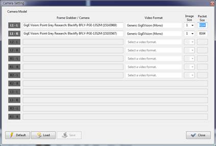
- Camera Setting
Sets the camera type, connection port, exposure, and others
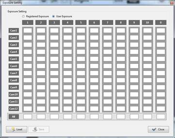
- Exposure Setting
Sets the user exposure for each type of camera
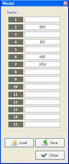
- Model
Input the car mode information, and press the “Save” button to store it.
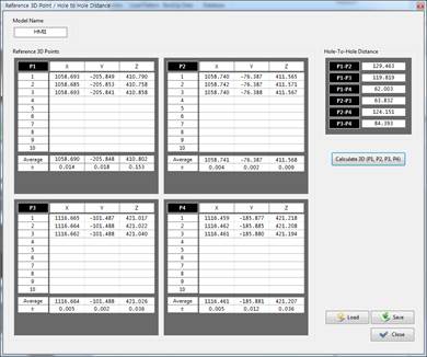
- Reference Points
Registers the position of the workpiece in relation to the measured four points as the reference position
- Auto 3D Correction
When “All Points” is selected, the measured 3D data will be calibrated and outputted. On the other hand, when “Non-Use” is selected, the uncorrected data will be outputted. The default is “Non-Use.”
- Shift Offset Setting
Set the shift offset for each model.

- Limit Setting
Set the range of the measured data and the error range of the distance between the measured feature points.
- Limit
The “Moving Distance Limit” represents the distance limit within which the measured feature points can move in space. The “Hole-to-Hole Distance Error” represents the error threshold between the measured feature points. If the 3D position of the workpiece moves beyond the “Moving Distance Limit” compared with the reference car body, NG will be outputted. If the distance between the feature points goes beyond the threshold value, NG will also be outputted.

- Password
Execute password change.

- File Management
Set the error generation image saving cycle and the deletion time. Considering that data deletion could cause a significant load on the system, it is recommended to set the deletion time at the early hours when the robot is not in operation.

n Calibration
Loads the camera calibration program, and calculates the relationship between the robot and the camera
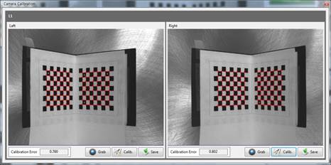
- Camera Calibration
The stereo camera calibration execution dialog will be loaded, and the camera projection matrix will be calculated. Clicking the [Save] button will save the projection matrix
- Automatic Camera Calibration
Executes stereo camera calibration automatically, and calculates and saves the camera projection matrix
- Robot-Camera Calibration
Calculates the relationship between the calibration plate, which is used for camera calibration, and the robot

- Hand-Eye Calibration
Calculates the relationship between the robot and the camera attached to it

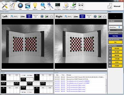
n Grab
Every time you click, it captures currently shown image.
n Live Display
“Continuous image” will be displayed from the installed camera.
n Exposure
Provides three types of autoexposure mode
- Registered Exposure
Acquires the image by applying the exposure used when registering the pattern
- Auto Exposure
Changes the exposure automatically to ensure that the brightness of the image, which is used when registering the pattern, would be similar to that of the current image When this mode is used, the image acquisition speed will slow down.
- User Exposure
Acquires the image by applying the exposure used by the user
n Search
When there is a pattern registered already, pattern recognition will be performed once after the image is acquired.
n 3D
When there is a pattern registered already, pattern recognition will be performed once after the image is acquired. After that, the 3D coordinate value will be calculated.
n Disp. Option
Decides whether to display the output data of the result to be displayed on the image window after the pattern is recognized
- Score
Displays the matching ratio of the pattern recognition result
- Pattern Region
Displays the pattern recognition region
- Coordinate Axes
Displays the coordinate axis of the pattern recognition
- Origin
Displays the origin of the pattern recognition
- Center and Scale
Maintains the exposure set in the camera setting window
- Center Guide Line
Displays a cross at the center of the image
n Load Pattern
Loads the registered pattern
n BackUp Data
Saves the currently set pattern data and the calibration data into the “C:*HRVision Stereo*Backup” folder
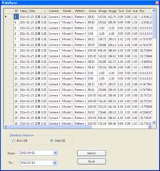
n DataBase
Displays a search window for the error data base and the measured data base
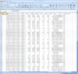
The search data can be displayed in connection with the “Microsoft Excel” program.
n Manual/Auto
Change the manual/auto mode. In the auto mode, it is impossible to operate all buttons, and they can be operated through communication with the PLC and the robot.