2.1. Hardware installation
2.1. Hardware installation
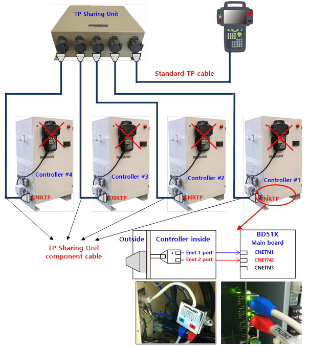
Individual teach pendants need to be connected to corresponding controllers through the teach pendant sharing unit.
The following shows the overall configuration that uses the sharing unit.
The following shows the detailed sequence for connecting hardware.
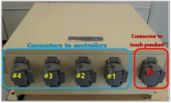
1. Connect a teach pendant that is to be shared to the TP connector at the right side of the above figure.
2. Make a connection between the TP connector of the #1 controller and the #1 connector on the above figure by using the connection cable that is a component of the sharing unit.
The sharing unit connection cable has the same specification of the general TP cable. Both ends are in the form of being connected to the teach pendant connectors.
3. The Ethernet divider at the teach pendant connection cable section inside the controller needs to be used to connect the Ethernet for the teach pendant and the Ethernet for the cooperation control individually to the main board (refer to the figure)
4. Power on the controller and the TP sharing unit, and execute the ‘function setting and ID assignment’ process.