5.1. Signal Input and Output
5.1. Signal Input and Output
To execute the simulation of signal input and output inside of ROBCAD, signals between various robots or devices should be defined in advance.
The SOP (Sequence of Operation) function of ROBCAD is used for executing the simulation of various robots or devices. Please refer to the ROBCAD manual or help file for details on using SOP.
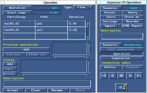
Figure 5.2 Sequence Of Operations menu
Open the SOP dialog box and create a new sequence and a new operation.
In the operation dialog box, select a robot from type list and add the robot and the corresponding path name inside the Procedure Matrix (A table in the middle) by selecting them with the mouse. Creation is completed by clicking Accept, and then clicking Confirm.
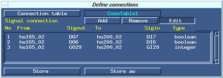
Figure 5.3 Define connections dialog box
Click the [Define] button of the Connection Table row to open the <Define connections> dialog box, then click the [Connection table] button to define a new table. Click the [Add] button continuously to define signal items.

Figure 5.4 Example of defining a signal item
For example, when defining a signal item as shown in [Figure 5.4], DO7 signal of hs165_02 will be connected to DI7 of hs200_02. After the [Accept] button is clicked, the pair of signals defined in the connection table will be added.
The name of a signal should be a pair of DO/DI or a pair of GO/GI. Set Boolean for the signal type of DO/DI and Int for the signal type of GO/GI.
By clicking the [Simulation] button in the <Sequence Of Operations> menu, a dialog box will be displayed as shown in [Figure 5.5], and the simulation of sending and receiving signals can be executed by clicking the Play button.
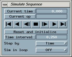
Figure 5.5 Simulate Sequence dialog box
NOTE Step button and accuracy
If the step button is used to execute a single step of robot motion, the tool end will not stop precisely at the target location, and will stop at a distance (zone) of accuracy setting. For the tool end to stop precisely at the target location, the accuracy distance (or axis angle) should be set to 0. |
NOTE Simulation of circular arc interpolation
Circular arc interpolation of the Hi5 controller and the Hi5 OLP package will be executed using 2 rules.
Rule 1. If the next step of the target is C, use it as a reference point.
Rule 2. If the next step of target is not C, use the previous step as a reference point
ø If step1 is a circular arc interpolation and the robot tool end is located from a far distance, a motion error may occur while describing a very large circle.
ø If the target is the final step, the previous step will be set as a reference point. |

