9.2. User coordinate
9.2. User coordinate
HRSpace3 supports maximum of 10 user coordinates. The advantage of using this function is that because you can specify a job’s RefPos as the target work not as the robot, so the job will move with the target work when the work is moved.
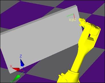
For example, let’s try to teach the steps in the user coordinate for the 4 corner surfaces of the rectangular panel as shown below.
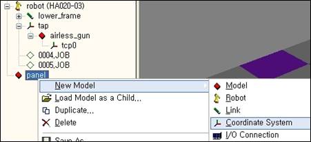
First, create the user coordinate as the child model of the panel and set the name to ‘crd_panel’.
The coordinate will be created at the origin location of the panel as shown below. If needed, edit the model properties of the coordinate to adjust the location/direction of the origin.

Open mini T/P of the robot and create new job. Tree window looks like as below.

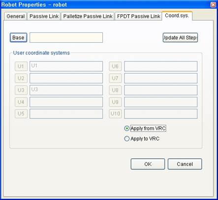
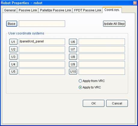
Now open Robot Properties and select Coordinate System tab. Click U1 button in User coordinate systems and click ‘crd-panel’ in tree window.
Choose one from two options as below to connect with a virtual controller.
Apply from VRC | The changes in user coordinate systems in VRC are immediately applied to the virtual controller. This is useful when you import onsite robots’ controller files and observe them on a 3-D screen or utilize virtual TeachPendant to practice operations. |
Apply to VRC | The changes in user coordinate systems on HRSPace3 are immediately applied to the virtual controller. This is useful when you create robot controller files by designing work cells on a 3-D screen. |
Click ‘OK’ button to close the dialog box.
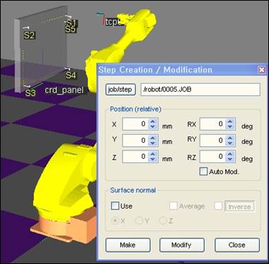
Teach steps on the surface of a panel by using Step Creation/Modification dialog box. At this time, dropdown list box on Teach bar for the coordinate system should be set to user1.

You may recognize coordinates displayed in Step Creation/Modification dialog box is user coordinate system, not robot coordinate system.
Run simulation when Teach is completed. If the result is normal, change the location/direction of the panel, press ‘Apply to VRC’ button in Coord. sys. Tab of Robot Properties dialog box, and run the simulation again. You may notice that tool end is moved to the same panel surface location before the change.

Virtual Controller may have 10 user coordinate systems at the most by setting control parameters. Select ‘Apply from VRC’ radio button if you need to utilize this information in HRSpace3. It creates coordinate system models as children models to the robot model and automatically set coordinate system properties of the robot model.
Later, when the values in user coordinate system are dynamically changed in a virtual controller, this is also applied to HRSpace3.