9.1. Traverse axis
9.1. Traverse axis
You can configure and simulate the traverse axis of the robot.
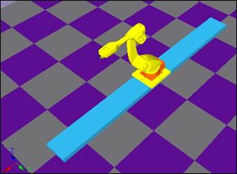
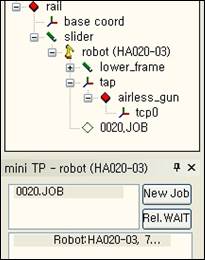
First, configure the rail, slider and robot as shown below. Rail is just a model but the slider is a moving part of the robot controller and must be made as a link.

Set the properties of each rail, slider and robot as shown in the below table and attach the tool to the robot.
Name | Location | Shape parameter | ||||
X | Y | Z | X | Y | Z | |
Rail | 0 | 0 | 0 | 5000 | 500 | 100 |
Base coordinate system | 0 | 0 | 150 | N.A. | ||
Slider | 0 | 0 | 100 | 600 | 600 | 50 |
Robot | 0 | 0 | 50 | N.A. | ||
Base and robot coordinate system is quite matched only except X value (when moving on the traverse axis), so we aligned the origins of base coordinate system and robot coordinate system (when the traverse axis value is 0).
Because the origin coordinate of the robot based on the origin of the rail is (0, 0, 150), the location of the model properties of the base coordinate must also be (0, 0, 150). (Rail height 100mm) + (Slider height 50mm) = 150mm )

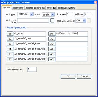
Specify the additional axis 1 of the robot as the traverse axis. Open the robot properties window.
n Set the total number of axes to 7 and number of additional axes to 1.
n Click on the A1 (Additional axis 1) button and click on the slider from the tree window.
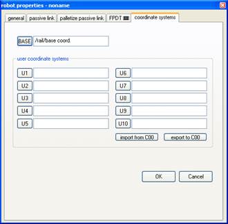
n Click on the base button and click on the base coordinate system in the tree window.
Now, click on OK to close the robot properties window.
It displays a message that says you need to initialize VRC because axes are changed. Click ‘OK’ button.

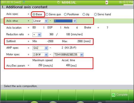
A message as below is displayed and virtual TeachPendant is automatically open. Go to the setting screen in the message and set additional axis settings of 7th axis. As you can see the picture as below, set Axis spec to Base, set ‘Axis struc’ to X, adjust ‘Softlimit’ and ‘Acc/Dec param’ appropriately, and press [F7: Complete] key.

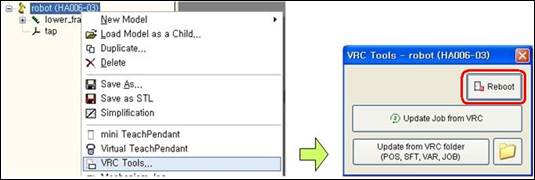
Save the document and reboot VRC to apply the settings.
In order to apply the setting, save the document and reboot the VRC.

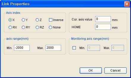
Open Link Properties dialog box of a slider. Since the robot should move to the left and right along with X axis, set Axis index to X and set the range of the axis.
Now let’s create work. First, create job with mini T/P.
Set the coordinate system on TeachBar to Base. Steps that are the robot’s coordinate system move along with the movement of the robot’s traverse axis.

Teach by using Record button while moving the traverse axis shown as below.
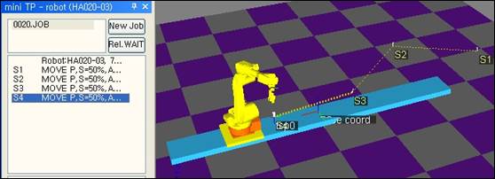
Confirm the moves by executing the simulation when Teach is completed.