4.3.2. PC Side Setting
4.3.2. PC Side Setting
First, you must select Ethernet as the communication method. When you click on the  button from the Tool Bar or select 『Tool (T) – Option (O)』 from the menu, the option dialog box will be displayed.
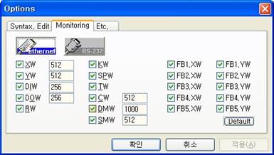
Figure 4.19 Option Dialog Box
(1) After selecting the monitoring tab from the option dialog box as shown in [Figure 4.19], press the  button and then the OK button to close the dialog box. The communication method will be selected to Ethernet.
(2) Next you must set up the parameter including IP address of Ethernet and port number etc. When you click on the  button from the Tool Bar or select『Tool (T) – Comm Setup... (C)』 from the menu, the Ethernet setting dialog box will be displayed as shown in [Figure 4.20].
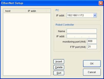
Figure 4.20 Ethernet Communication Setting Dialog Box
(3) First, open the list box of the IP address in the PC group box as shown in [Figure 4.21] and select the IP address of the PC itself. If there are 2 or more Ethernet devices installed on the PC, this is the process to designate which device to communication with.
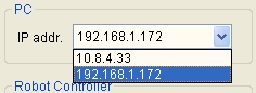
Figure 4.21 Select PC IP Address
(4) Now register the frequently accessed controller in this dialog box. The controller can be registered as follows.
① Enter the Host Name (Controller name or number) and the IP address in the right block. After entering the information, click on the [Add (I)] button to add to the left list. Repeat this process to enter all the controllers as shown in [Figure 4.22].
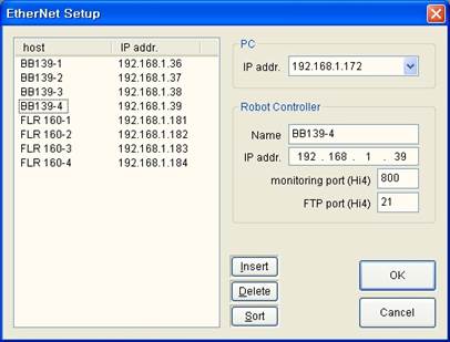
Figure 4.22 Prepare Controller IP Address List
② To delete one item from the list, select the item and then click on the [Delete (D)] button.
③ To sort the items on the list in the order of 123 and ABC, click on the [Sort (S)] button.
④ To edit the item on the list already entered, select the item and change the value on the right side. And then click on a different item to reflect the changes.
⑤ After selecting the item you want from the list, click on the [OK] button. The selected item will be shown as the host to connect and the dialog box will be closed. At this time, the prepared list will be saved as the text file named “ENetSetup.dat” in the directory where the HRView execution file is located.
(5) [Figure 4.23] shows an example of the “ENetSetup.dat” file opened in Notepad.
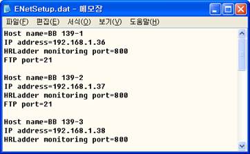
Figure 4.23 Example of “ENetSetup.dat” File in Notepad
(6) The name and IP address of the item selected from the Ethernet setting dialog box will be display on the PLC Control Bar as shown in [Figure 4.24]. This is the host to connect.

Figure 4.24 Display of Host Name and IP Address on PLC Control Bar