4.2.2. Controller Side Loopback Test Method
4.2.2. Controller Side Loopback Test Method
(1) From the Teach Pendant of the robot controller, select 『[F2]: System』 → 『2: Control Parameter』 → 『3: Serial Port』 → 『1: Serial Port #1』(Or, 『2: Serial Port #2』) screen and press the 『[F1]: Communication Test』 button.
(2) In accordance with the direction on the screen, short circuit the 2-3 pin of the RS-232C terminal of the controller cabinet as shown in [Figure 4.12] A.)
 (A)
(A)  (B)
(B)
Figure 4.12 Controller Cabinet Side RS-232C Transmission Short Circuit
(3) If you see the message shown in [Figure 4.13] when you press the [ENTER] key, it is normal.
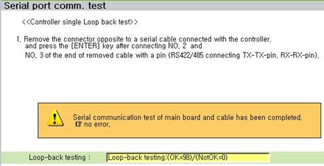
Figure 4.13 Normal Loopback Test Result
(4) In case of an error, a message saying that it is moving to the 2nd stage will be displayed as shown in [Figure 4.14]. In accordance with the direction on the screen, short circuit the 2-3 pin of the main board RS-232C terminal.
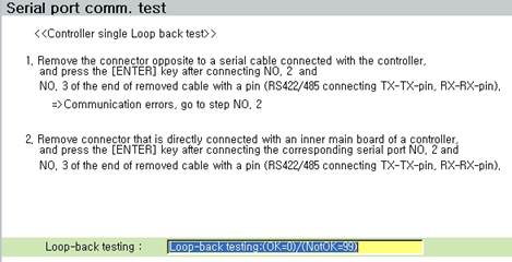
Figure 4.14 Main Board Side RS-232C Transmission Short Circuit

Figure 4.15 Main Board Side RS-232C Transmission Short Circuit
(5) If you see the following message when you press the [ENTER] key, it means that there is no problem with the main board. Check the cable connection with the control box connected from the inner RS-232C terminal to the main board.
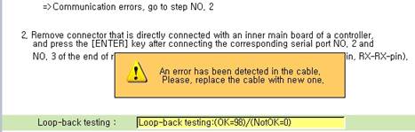
Figure 4.16 RS-232C Cable Check Message within Control Box
(6) If you see the following message when you press the [ENTER] key, it means that there is an problem with the main board. Try replacing the main board.
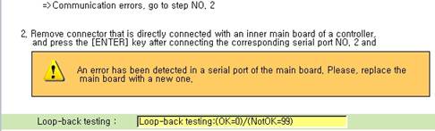
Figure 4.17 Main Board RS-232C Error Message