3. Input / Output Diagram
Input and Output Diagram of Hi5 Robot Controller is as below.
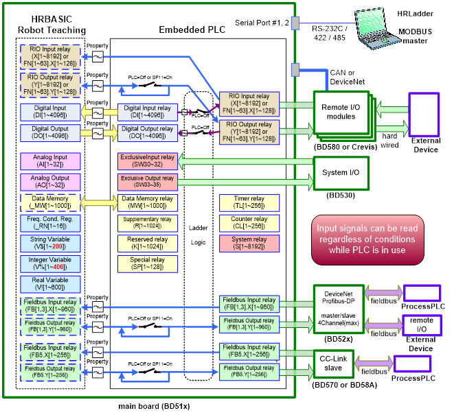
Figure 3.1 Input / Output Diagram
l System Memory from the above figure is reserved for special purpose. The purpose may change in future, depending on the Controller’s version.