5.2. Examples of GX developer setting (CC-Link V2.0)
5.2. Examples of GX developer setting (CC-Link V2.0)
(1) When you double click on the 『Network param』item from the GX Developer project, the 『Network parameter』message box will be displayed. Here, click on the 『CC-Link』button.
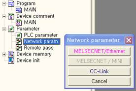
Figure 5.2 Network Parameter Message Box
(2) Example with 1 master module installation on the PLC is displayed in [Figure 5.3]. According to the Figure 5.4, please set the Mode as Remote net (Ver.2 mode) and set the number of slave for all connect count. Then set a relay start which will map RX, RY, RWr, or RWw.
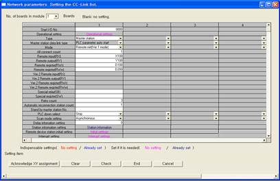
Figure 5.3 CC-Link Network Parameter Setting

Figure 5.4 Mode and Relay Start Point Setting
(3) Click on “Station information”.

Figure 5.5 Station information
(4) For the station that corresponds to Hi5 Controller, “Station type” needs to be set to 『Ver. 2 Remote device station』and “Expanded cyclic setting” needs to be set to 『quadruple』. Also please set the 『Exclusive station count』to matches with the station quantity setting of BD57x.
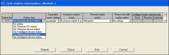
Figure 5.6 CC-Link Station information
(5) Select the menu item of 『Online - Write to PLC』. When you check the 『PLC/Network/ Remote password』item and click on the 『Execute』button, the setting will be saved to the PLC.
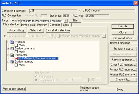
Figure 5.7 Write to PLC Message Box