5.3.2.2. Digital Output
5.3.2.2. Digital Output
The following Figure and Table show the pin composition of connector CNOUT for digital output. For the 32-point output pin, different power can used for 8 output signals.
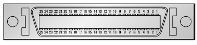
Figure 5.14 CNOUT Connector (3M MDR 10250-52A2JL) of the Public IO Board (BD582)
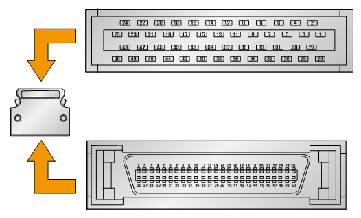
Figure 5.15 3M MDR 10150-3000VE (HOOD;10350-52F0-008) of the CNOUT Connector Plug of the Public IO Board (BD582)
Table 5‑6 Pin Configuration of the Digital Input Connector CNOUT of the Public IO Board (BD582)
Pin Number | Signal Name | Function Description (Expansion Board/Basic Board) |
1 | DO01 | Public output 1 |
2 | DO02 | Public output 2 |
3 | DO03 | Public output 3 |
4 | DO04 | Public output 4 |
5 | DO05 | Public output 5 |
6 | DO06 | Public output 6 |
7 | DO07 | Public output 7 |
8 | DO08 | Public output 8 |
9 | COMOUT0 | External power input (User power): COMMON (For DO01~DO08) |
10 | ||
11 | DO09 | Public output 9 |
12 | DO10 | Public output 10 |
13 | DO11 | Public output 11 |
14 | DO12 | Public output 12 |
15 | DO13 | Public output 13 |
16 | DO14 | Public output 14 |
17 | DO15 | Public output 15 |
18 | DO16 | Public output 16 |
19 | COMOUT1 | External power input (User power): COMMON (For DO09~DO16) |
20 | ||
21 | N.C | Not used |
22 | N.C | Not used |
23 | N.C | Not used |
24 | N.C | Not used |
25 | N.C | Not used |
26 | N.C | Not used |
27 | N.C | Not used |
28 | N.C | Not used |
29 | N.C | Not used |
30 | N.C | Not used |
31 | DO17 | Public output 17 |
32 | DO18 | Public output 18 |
33 | DO19 | Public output 19 |
34 | DO20 | Public output 20 |
35 | DO21 | Public output 21 |
36 | DO22 | Public output 22 |
37 | DO23 | Public output 23 |
38 | DO24 | Public output 24 |
39 | COMOUT2 | External power input (User power): COMMON (For DO17~DO24) |
40 | ||
41 | DO25 | Public output 25 |
42 | DO26 | Public output 26 |
43 | DO27 | Public output 27 |
44 | DO28 | Public output 28 |
45 | DO29 | Public output 29 |
46 | DO30 | Public output 30 |
47 | DO31 | Public output 31 |
48 | DO32 | Public output 32 |
49 | COMOUT3 | External power input (User power): COMMON (For DO25~DO32) |
50 |
The output specification of each port is as follows.
l Output component: Photo MOSFET output
l Rated output = 125mA (Continuous load current), 24V DC
l (-) Common output voltage = 0V DC (OPEN COLLECTOR)
The user connects the output signal through the method shown in Figure 5.16 below. First, connect the COMMON signal to the public IO board (BD582), and then connect each signal to the output pin depending on the usage. The power can be differently used by each 8-output port unit.

Figure 5.16 Method for Connection of Output Signals of the Public IO Board (BD582)