5.3.2.1. Digital Input
5.3.2.1. Digital Input
The following Figure and Table show the pin composition of connector CNIN for digital input. For the 32-point input pin, different power can be used for 8 input signals.

Figure 5.11 CNIN Connector (3M MDR 10240-52A2JL) of the Public IO Board (BD582)
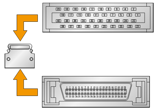
Figure 5.12 3M MDR 10140-3000VE (HOOD:1030-55F0-008) of CNIN Connector Plug of the Public IO Board (BD582)
Table 5‑5 Pin Configuration of Digital Input Connector CNIN of the Public IO Board (BD582)
Pin Number | Signal Name | Function Description (Expansion Board/Basic Board) |
1 | DI01 | Public input 1 |
2 | DI02 | Public input 2 |
3 | DI03 | Public input 3 |
4 | DI04 | Public input 4 |
5 | DI05 | Public input 5 |
6 | DI06 | Public input 6 |
7 | DI07 | Public input 7 |
8 | DI08 | Public input 8 |
9 | COMIN0 | External power input (User power): +24 V (For DI01~DI08) |
10 | ||
11 | DI09 | Public input 9 |
12 | DI10 | Public input 10 |
13 | DI11 | Public input 11 |
14 | DI12 | Public input 12 |
15 | DI13 | Public input 13 |
16 | DI14 | Public input 14 |
17 | DI15 | Public input 15 |
18 | DI16 | Public input 16 |
19 | COMIN1 | External power input (User power): +24 V (For DI09~DI16) |
20 | ||
21 | DI17 | Public input 17 |
22 | DI18 | Public input 18 |
23 | DI19 | Public input 19 |
24 | DI20 | Public input 20 |
25 | DI21 | Public input 21 |
26 | DI22 | Public input 22 |
27 | DI23 | Public input 23 (Signal for external operation) |
28 | DI24 | Public input 24 |
29 | COMIN2 | External power input (User power): +24 V (For DI17~DI24) |
30 | ||
31 | DI25 | Public input 25 |
32 | DI26 | Public input 26 |
33 | DI27 | Public input 27 |
34 | DI28 | Public input 28 |
35 | DI29 | Public input 29 |
36 | DI30 | Public input 30 |
37 | DI31 | Public input 31 |
38 | DI32 | Public input 32 |
39 | COMIN3 | External power input (User power): +24 V (For DI25~DI32) |
40 |
The input specification of each port is as follows.
l Input port component: AC input photocoupler
l Input impedance= 3 ㏀
l (+) Common input voltage = 24 VDC
l (-) Common input voltage = 0 VDC
The user connects the input signal through the method shown in Figure 5.13 below. First, connect the user power +24 V and ground wire to the public IO board (BD582), and then connect each signal to the input pin, depending on the usage. The power can be differently used by the 8 input port units.
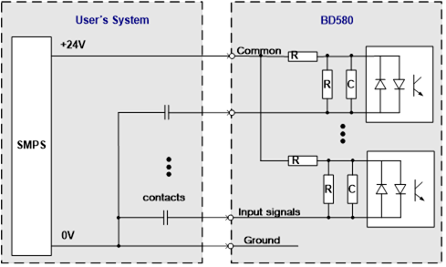
Figure 5.13 Method for Wiring Input Signals of the Public IO Board (BD582)