7.2.1.4. Error output to the outside
7.2.1.4. Error output to the outside
This function outputs the detected error number to the external party through the serial port.
n Serial output
Use the serial port (RS232C) to output ASCII code to the external device.
Output formats are
1st byte : “$”
2~6th byte : “ERROR”
7th byte:“ “ (Blank)
8~11th byte : Error number
12th byte : CR
13th byte : LF
Ex) For error 0101 (E0101)

n Number pre-designation output
Output of pre-designated number outputs the error/warning number of the signal assigned『[F2]: System』 → 『2: Control parameter』 → 『2: Input/output signal setting』 → 『4: Output signal assign』.
Table 7‑1 Output of signal assignment by assigned signal
Assigned signal name | Whether to assign and how many | |
8 bit | 16 bit | |
Error/Warning output selection | ○ : 1 | × |
Error/Warning output STRB | ○ : 1 | × |
Error/Warning output Bit | ○ : 8 | ○ : 16 |
System error, operation error | ○ : 1 | ○ : 1 |
Warning generated | ○ : 1 | ○ : 1 |

l If the warning generation output signal is ‘0’, it is an error number. If it is ‘1’, it is a warning number.
l When a warning is generated, system error signals as well as operation error signals will not be turned on.
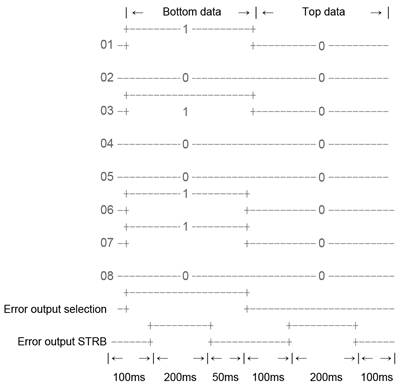
① 8 bit – Convert the error/warning number to a binary number and divide the bottom 8 bit and top 8 bit for output. The signal to classify the bottom and top data is the error/warning output selection signal. The strobe function that decides the data check timing is the error output STRB signal.
Ex) In case of E0101, the timing as well,
(10110 = 006516 = 0000 0000 0110 01012)
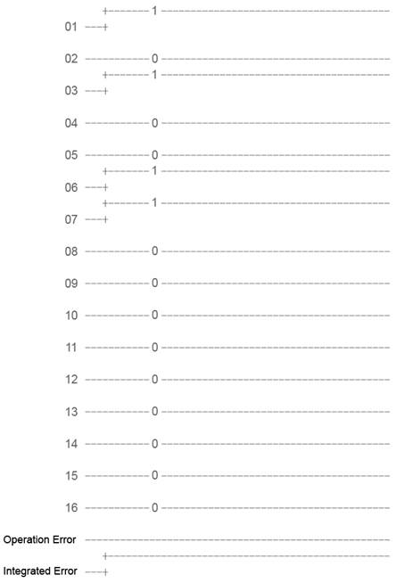
② 16 bit – Convert the error number into 2digit number and output the 16 bit data.
The strobe signal that decides the data check timing
- System error => Overall error
- Operating error => Operational error or above.
Ex) In case of E0101, the time as well (System error)