3.1. Pattern Registration Procedure
3.1. Pattern Registration Procedure
This section describes the process of registering patterns. |
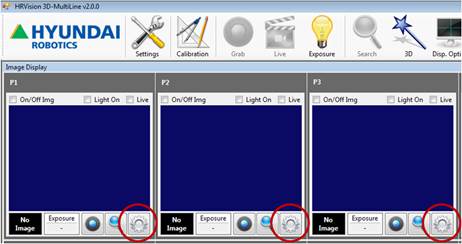
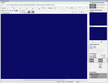
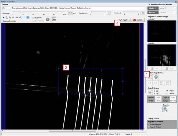
[Step 1] (1) If the camera is wrist-held, move it to the point for pattern registration. (2) When the point’s pattern registration button (encircled in the above figure) is clicked, a window will appear as shown in the following figure:
|
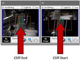
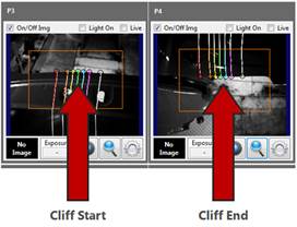
[Step 2] (1) In pattern registration, select the camera location so that the bent/cut surface of the workpiece can be clearly detected. (2) In the camera image, the starting point of the bent/cut surface will be expressed in [Cliff Start], and the end point will be expressed in [Cliff End]. (3) As shown in the above figure, a [Cliff Start] for detecting the starting point of a line pattern and a [Cliff End] for detecting the end point must be registered. (4) When the line pattern projected on the workpiece overlaps the background, no [Cliff Start] or [Cliff End] will be detected. Therefore, the camera location must be adjusted so that [Cliff Start] and [Cliff End] can be clearly distinguished. (5) The end point will not be detected clearly depending on the camera location if the curvature (R value) of the bent surface is large. Therefore, it is recommended to detect a surface of a small curvature or a cut surface. |
[Step 3] (1) Select a model number.
|
[Step 4] (1) Click [Live Display], and check whether the focus of the camera on the projected pattern is clear and the position is adequate. (2) Turn off the line pattern light of the pattern projector, and disable the [Light On] checkbox. For example, set [DO3=0] to turn off the line pattern light if the On/Off status of the pattern projector is controlled by DO3 of the robot controller. (3) Click the [Grab] button to acquire an image. (4) Turn on the line pattern light of the pattern projector, and enable the [Light On] checkbox. For example, set [DO3=1] to turn on the line pattern light if the On/Off status of the pattern projector is controlled by DO3 of the robot controller. (5) Click the [Grab] button to acquire an image. (6) If images are acquired properly when the projector is on and off, an image with the line pattern light off will appear in [Light Off], and an image with the light on will appear in [Light On], as shown in the following figure.
|
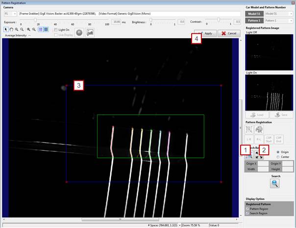
[Step 5] (1) Click the pattern setting button. (2) Adjust the pattern setting area using the mouse so that the starting point or the end point of the line pattern appears in the image window. (3) When the [Apply] button is clicked, the line patterns will appear in various colors, and the pattern setting area will be indicated by a green rectangle, as shown in the following figure.
|
[Step 6] (1) Click the [Cliff Start] or the [Cliff End] button depending on the part to be detected. The starting point or the end point of the line pattern will be indicated by a [+] mark. (2) If the location of the starting point or end point is slightly offset because of excessive light exposure or if a problem occurs in which a line pattern remains on the background, raise the [Peak Threshold] value to an adequate level, as shown in the following image. (This is supported only in a specific version or higher.)
(3) If the desired part is not indicated, repeat the above procedure. (4) If the starting point or end point is properly detected, click the [Apply] button. The following figure shows an example in which the starting point of a line pattern is detected.
|
[Step 7] (1) Set the search area by clicking the [1 Pattern Search Area] button. (2) Expand the search area to match the image size by clicking the [2 Maximize Area] button. (3) Considering the movement range of the workpiece, adjust the pattern search area using the mouse so that it is slightly larger than the pattern setting area. (4) Clicking the [Apply] button will indicate the pattern search area in orange. |
[Step 8] (1) Click the [Search] button to check whether the registered pattern is properly detected. (2) If the pattern is properly detected, apply the previous procedure to all the remaining cameras.
|