1.2. BD525 Board Exterior
1.2. BD525 Board Exterior
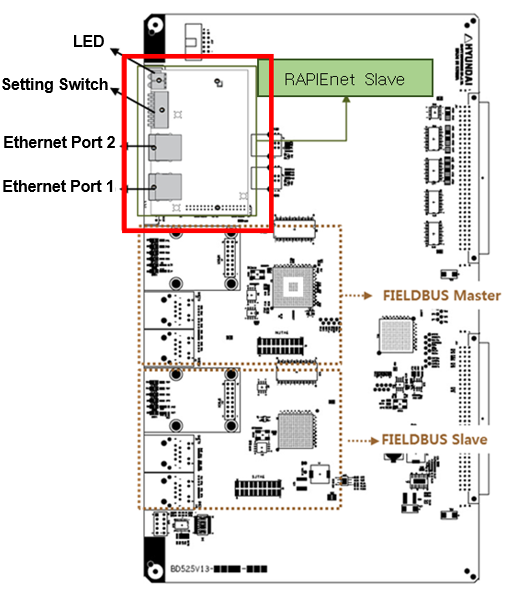
Figure1.1 RAPIEnet Communication Board
BD525 multi-protocol communication board can support up to three channels of industrial communication at the same time, including RAPIEnet slave as well as Fieldbus or Real-Time Ethernet master and slave. When it comes to the Fieldbus or Real-Time Ethernet other than RAPIEnet, you need to refer to the function manual about the relevant protocol.
The RAPIEnet slave communication board is mounted on the BD525 board in the form of a piggyback and has a setting switch (using the default settings), four LEDs, and two Ethernet ports.
※ For more information) The RAPIEnet slave can only be supported when the BD525 hardware version is V1.3 or higher.
(1) Setting Switch
You can set the station number using the setting switch. However, the basic specification for operation is that the station number needs to be set through a TP. Accordingly, it is needed to set all pins, #1–8, to 0. (Please be informed that you can perform the setting using the same station number that you may use through the setting switch.)
Table 1‑1 Setting Switch
| Description | Remarks | ||
PIN No. | Usage | Value | ||
1–8 | Station No. | 0 | Setting of the station number through the shared memory | When a change is made, it will be reflected after the power is reset. |
1–119 | Station number | |||
120 onward | Parameter error | |||

(2) LED
Table 1‑2 LED Status
| Description | ||
No. | Display | Status | |
1 | Run | Off | - Power off |
Green | - Normal operation | ||
2 | SEMA | Off | - Shared memory Semaphore released |
Green | - Shared memory Semaphore acquired | ||
3 | PRM/Flash ERR | Off | - Parameter setting is normal. No abnormality with the flash memory. |
Red | - Parameter setting is abnormal, or there is an error with the flash memory | ||
4 | ERR | Off | - Normal operation |
Red | - Own station is abnormal. There is an IP duplicate station. | ||
Red blinking | - Link error | ||
