3. Input / Output Diagram
Input and Output Diagram of Hi5a Robot Controller is as below.
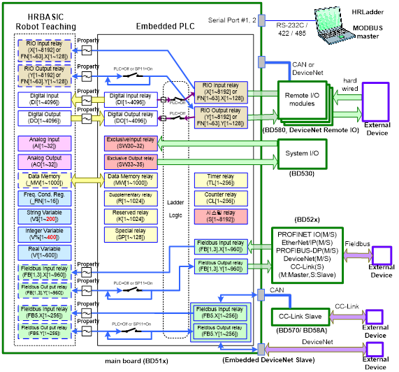
Figure 3.1 Input / Output Diagram
n Even when PLC is used, turning on SP11 will make it possible to control the relays for RIO output (Y[1~8192], FnN[1~63].Y[1~128]) or for the field bus output (FB[1,3,5].Y[1~960]) directly from the robot job program (HRBASIC).
However, in case of input relays (X[1~8192], FN[1~63].X[1~128], FB[1,3,5].X[1~960]), it is possible to read them from the robot job program always regardless of the use of PLC.
n System Memory from the above figure is reserved for special purpose. The purpose may change in future, depending on the Controller’s version.