5.4.3. Indication and Setting Units
5.4.3. Indication and Setting Units
Various LEDs are used to display the communication status of the CC-LINK line. The contents indicated by the LEDs are marked on the board as follows. In addition, for the station number and communication speed setting of the CC-link, DIP switches are used and the contents relevant to them are also marked on the board as follows.
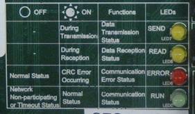
Figure 5.24 LED and Detail of Communication Status Indication of CC-LINK Board (BD570)
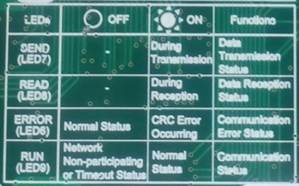

Figure 5. 5.25 Led For Displaying the Communication Conditions of the CC-link Board (Bd570v20) and the Information
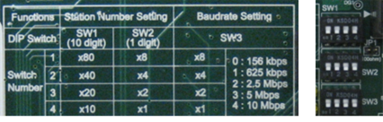
Figure 5.26 Setting Station Number and Communication Speed of the CC-LINK Board (BD570)
Table 5-10 How to Set the CC-link Station Numbers and the Data Rate (BD570V20)
Switch Name | Use | Form | How To Set | Set During Forwarding |
Sw1 | Station No. (10 Units) |
| Setting Station Number= (Set Value Of Swz1 X 10) + Set Value Of Swz2 | “0” |
Sw2 | Station No. (1 Unit) |
| “1” | |
Sw3 | Data Rate |
| 0 : 125 Kbps 1 : 625 Kbps 2 : 2.5 Mbps 3 : 5.0 Mbps 4 : 10 Mbps | “4” |


Figure 5.27 Method for Setting of the Number of Stations of the CC-LINK Board (BD570)
Table 5-11 How to Set the Number of the CC-link Station Occupied By the CC-link Board (Bd570v20)
Switch Name | Form | Switch No. | How To Set The No. Of Station Occupied | Set During Forwarding | |||
1 | 2 | 3 | 4 | ||||
SENYU |
| 2 (SENYU1) | Off | Off | On | On | On |
1 (SENYU0) | OFF | ON | OFF | ON | ON | ||
