3.2.1. Stereo Camera Calibration
3.2.1. Stereo Camera Calibration
This is a camera calibration process to match camera coordinate system and common one of the process.
“HRVision 3D-MultiCam” performs the calibration using the following calibration board.

While the calibration board above is placed in the visual area of stereo camera, stereo image is recorded. Recorded stereo image is saved to “C:*HRVision MultiCam*Image” folder.
In “Calibration” menu of “HRVision 3D-MultiCam” menu, click “Camera Calibration” menu to perform the following “Hyundai Heavy Industry Stereo Camera Calibration Program” (Calibration Program).
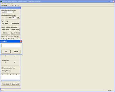
“Calibration Program” can be used only by entering correct password. The password will be provided by the seller of “HRVision 3D-MultiCam SW.” If wrong password is entered, the program is closed.
The figure below shows password prompt.

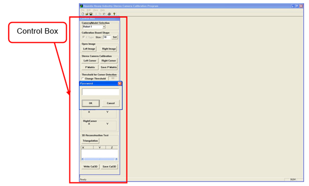
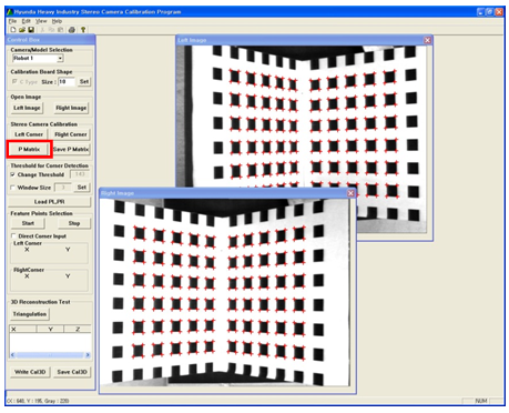
With correct password, all the functions of “Calibration Program” can be used as shown below. The functions of “Calibration Program” can be executed by controlling the “Control Box.”
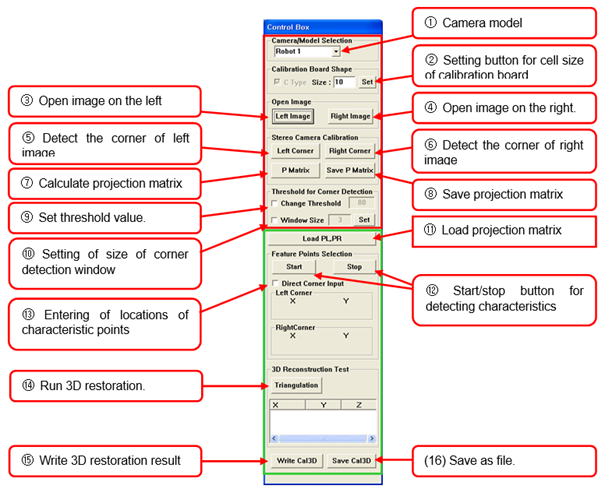
The camera calibration procedure is as follows.
First, select the number of stereo camera with “① Camera model” combo box of Control Box according to the location of robot.
With “② Setting button for cell size of calibration board”, enter the cell size of used calibration board. According to the lens specifications and installation environment, the size of calibration board can be 10mm, 15mm, and 20mm while the 10mm one is generally used.
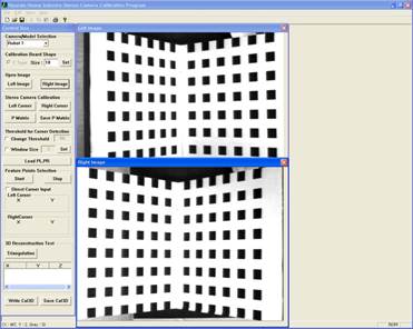
With “③ Left Image” button, open the left stereo image of the calibration board. The image is saved to “C:*HRVision MultiCam*Image” folder. The selected image is loaded to the calibration program.

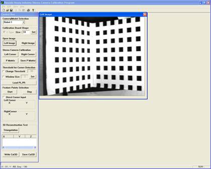
With “④ Right Image” button, open the right stereo image of the calibration board. The image is saved to “C:*HRVision MultiCam*Image” folder. The selected image is loaded to the calibration program.

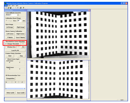
To calculate the corner points existing in the calibration board of the image, set corner detection threshold value. Click “⑨ Change Threshold” check box. Locate the mouse pointer on the white area of left image and double click it.
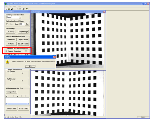
As shown in the figure, locate the pointer on the black area and double click it to automatically configure the threshold value to detect corners.

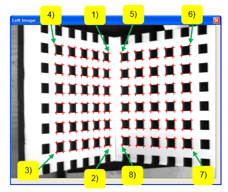
Stereo camera calibration can be performed using the corner points of black rectangles for the same areas between left and right images. The procedure to obtain corner points of each image is as follows.
Click “⑤ Left Corner” button and then the contour of the black rectangle of left image in the following order. Click the 8 points in the order to automatically detect the corner of black rectangle in the area.
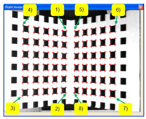
Click “⑥ Right Corner” button and the contour of the black rectangle of left image in the following order. Click the 8 points in order to automatically detect the corner of black rectangle in the area.
If the detected numbers of corner points are the same for left and right images, click “⑦ P Matrix” button. After the calculation is completed, the corner points become blue.
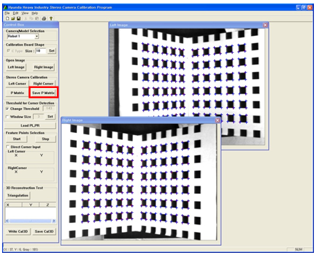
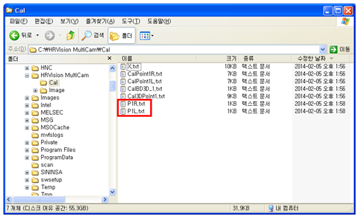
Click “⑧ Save P Matrix” button to save the projection matrix. Saved calibration data is saved to “C:*HRVision MultiCam*Cal” folder. Check if “P(No.)L.txt” and “P(No.)R.txt” files are created for the selected camera model. If the files are created, the camera calibration is completed.