3.2.2. Controller side loopback test
3.2.2. Controller side loopback test
(1) Enter 『[F2]: System』 → 『2: Control parameter』 → 『3: Serial port』 → 『1: Serial port #1』 (or, 『2: Serial port #2』) screen from teach pendant of robot controller and press 『[F1]: Comm. test』.
(2) Sort No. 2 pin and No.3 pin from RS-232C terminal of controller cabinet according to the direction on the screen as [Figure 3.12] A. (Short B together if the internal cable needs to be checked.)
 A
A  B
B
Figure 3.12 controller cabinet side RS-232C transmission and reception short
(3) If the message as [Figure 3.13] is displayed when pressing [ENTER] key, it is normal.
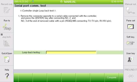
Figure 3.13 Normal loopback test result
(4) In case an error occurs, a message saying skipping over to the second step will be displayed as [Figure 3.14]. Short No.2 pin and No. 3 pin on the main board RS-232C terminal according to the direction.
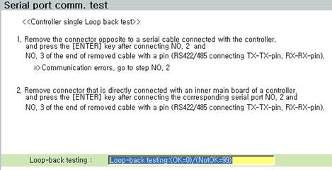
Figure 3.14 main board side RS-232C transmission and reception short

Figure 3.15 main board side RS-232C transmission and reception short
(5) If a message as below is displayed when pressing [ENTER] key, there will be no problem on the main board, so check cable wiring on the inside of controller cabinet from RS-232C terminal to the main board.
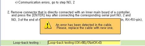
Figure 3.16 Checking message of RS-232C cable inside of terminal
(6) If the message below is displayed when pressing [ENTER] key, the main board has a problem, so replace the main board.
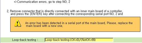
Figure 3.17 Main board RS-232C error message