3.1. EtherNet/IP adapter setting
3.1. EtherNet/IP adapter setting
It is required to set an IP address and the size of input and output data to use an EtherNet/IP adapter as shown in the following procedure.
(1) Select 『[F2]: System』 → 『2: Control parameter』 → 『2: Input/Output signal setting』 → 『14: Real-time Ethernet setting and diagnosis』.
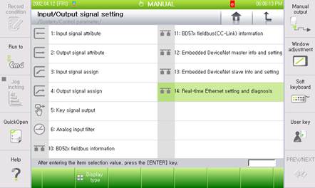
Figure 3.1 Real time Ethernet setting and diagnosis menus
(2) As the EtherNet/IP adapter corresponds to Channel 3, Use the 『[F3]: Previous』 or 『[F4]: Next』key to shift to Channel 3 and then check whether the Device Type shows “EtherNet/IP Adapter”.
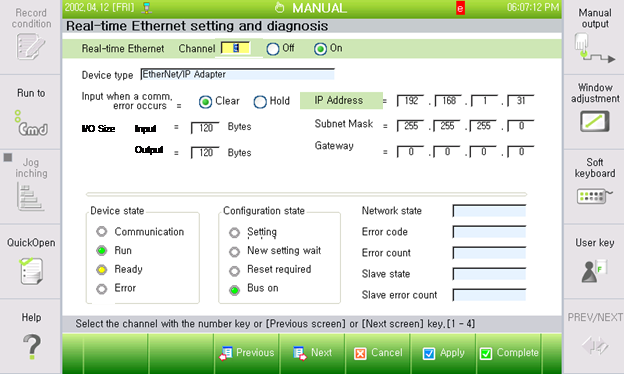
Figure 3.2 EtherNet/IP adapter setting screen
(3) Set the Ethernet information such as the IP address, the subnet mask and the gateway.

Figure 3.3 IP address setting screen
(4) Set the size of input and output data and the option for handling input data when a communication error occurs.

Figure 3.4 I/O setting screen
n Input when a communication error occurs:
This is an option for handling input data (FB3.X) when an EtherNet/IP communication error occurs. When it is set as “Clear”, all the input data will be cleared to be “0” and when it is set as “Hold”, the last valid value that is to be generated when the error occurs will be maintained.
n I/O size:
This is for setting the size of input and output data when it comes to the EtherNet/IP scanner. When it comes to the robot controller, the input corresponds to FB3.Y and the output corresponds to FB3.X. The default of the size of the input and output data is 120Byte.
(5) In order to use the EtherNet/IP adapter, shift it to the “On” position and then click the “Apply” or “Complete” button.

Figure 3.5 Function on/off setting screen
* Reference:
When the setting of the EtherNet/IP adapter changes, it is required to reset (Off → On) or reboot the robot controller to apply the newly set values.